Hardware overview
It is assumed that the reader is familiar with purpose and functionalities of MuxPi board from the Project overview.
The purpose of this page is to give the user general overview of the MuxPi board. Board assembly or flashing microcontrollers with firmware is not considered in scope of this document.
High Level Overview
The following diagram is meant to set a general picture of how MuxPi was built:

- White denotes MuxPi components (SOC, SBC, IC, etc.)
- Green components are various connectors on MuxPi board
- Red components are power sockets on MuxPi board
- Blue components are MuxPi’s user interface elements
- Yellow denotes ETH MuxPi connector to test server
Component description
- NanoPi NEO - is a Single Board Computer (SBC) based on Allwinner H3 (Cortex-A7). It features 1.2GHz quad core with 512MB of RAM. Currently MuxPi is compatible with NanoPi NEO v1.1, v1.2, v1.3.
- 4-wire UART level shifter - simple block of voltage level shifters for
connecting to DUT’s UART. Not pictured on the diagram above:
- UART voltage generator - allows to generate voltage in range from 0 to 5V.
- USB/UART SWITCH & ID - a block of componnets with dedicated USB connector. The component allows to control USB Vbus and ID, and allows to redirect USB data lines either to NanoPi’s USB or UART.
- STM32 - specifically STM32F030C6T6 is a Cortex-M0 based micro-controller
which supports NanoPi board with low-level functions. The module takes care
of:
- controlling SD-MUX module
- controlling DyPers
- handling User Interface elements (2x button, 2x LED, OLED Display)
- writing EDID [1] to DUT’s HDMI
- measuring DUT’s current draw
- handling NanoPi’s watchdog
- cooperating with add-ons (NanoPi NEO can also cooperate with add-ons
directly):
- measuring analog signals
- handling GPIOs
- Watchdog Timer - a simple timer that allows to restart of NanoPi board; timeout can be configured in a very wide range: milliseconds, seconds, minutes, hours… It also allows the STM32 to reset the NanoPi NEO when it becomes unresponsive.
- User Interface (Blue elements):
- red power presence LED
- yellow UART VCC presence LED
- blue SD card reader activity LED
- blue NanoPi NEO keepalive LED
- two monochrome (green and red) LEDs driven by NanoPi (accessible by user)
- two RGB LEDs driven by uC (accessible by user)
- 128x32 OLED display (accessible by user)
- 2 push buttons (accessible by user)
- USB HUB - 2 port USB hub with integrated microSD card reader. Downstream
ports are distributed to:
- 2xUSB-A connector
- add-ons connector
- USB-ETH converter
- USB->ETH - USB to Ethernet converter, connected to NanoPi onboard USB hub, used to connect MuxPi to DUT in order to eliminate need of external Ethernet switch.
- SD-READER - microSD card reader (part of USB HUB integrated circuit) connected to SD-MUX and NanoPi NEO in order to eliminate need of external one.
- SD-MUX - multiplexer of microSD card which allows to connect the card either to SD-READER or a DUT.
- 2x 2-channel DyPers (Dynamic jumPer) - a simple switch intended to programmatically connect jumpers or push buttons on a DUT.
- Power Control & Current Measurement - a circuitry which allows to:
- control power of a DUT using electromagnetic relay
- measure DUTs current draw using HAL effect current sensor which gives galvanic isolation from control logic
- MuxPi Power Control - simple circuitry giving two functionalities:
- generate 3.3V for internal needs
- enable/disable power supply for the main board, controlled by NanoPi (power supply for NanoPi is not controlled by this circuit)
- UART->USB - simple converter allowing user to directly connect to NanoPi’s NEO UART0 (debug port).
Standard connectors
The following connectors are standard thus it is assumed that no additional explanation is neccessary.
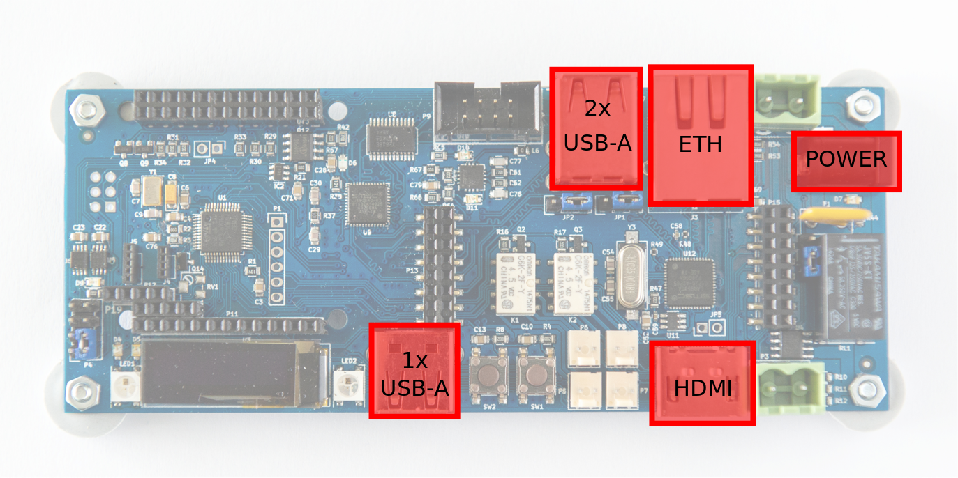
Above, you can find following connectors highlighted (listed clockwise):
- 2x USB-A - USB-A Host interfaces connected to NanoPi NEO through onboard USB HUB USB2640.
- ETH - standard RJ45 with built in LEDs and transformer. It is a connector for LAN9500A ETH<->USB converter which is connected to NanoPi through onboard USB HUB USB2640.
- POWER - 5V Power supply connector for MuxPi. Typical barrel receptacle 5.5/2.1 ensures that widely used, typical power adapters can be used to power the board. Power consumption of MuxPi should be less than 1A assuming no addons are connected.
- HDMI - Full-sized HDMI connector with connected only DDC channel wires, hot plug pin and GND/VCC pins. It is meant to be EDID injector into a DUT’s HDMI output. It is connected to Cortex-M0 microcontroller.
- 1x USB-A - USB-A Host interface connected directly to NanoPi NEO. Power supply of this connector is not controllable by NanoPi. It is always present.
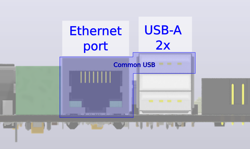
Note
The upper USB of the double USB socket, shares the same USB channel from USB HUB with ETH. (As shown on figure below) Jumpers located at the rear side of double USB connector allow to disconnect this USB from ETH and connect to add-on connector. Details on this topic are covered in Jumpers section.
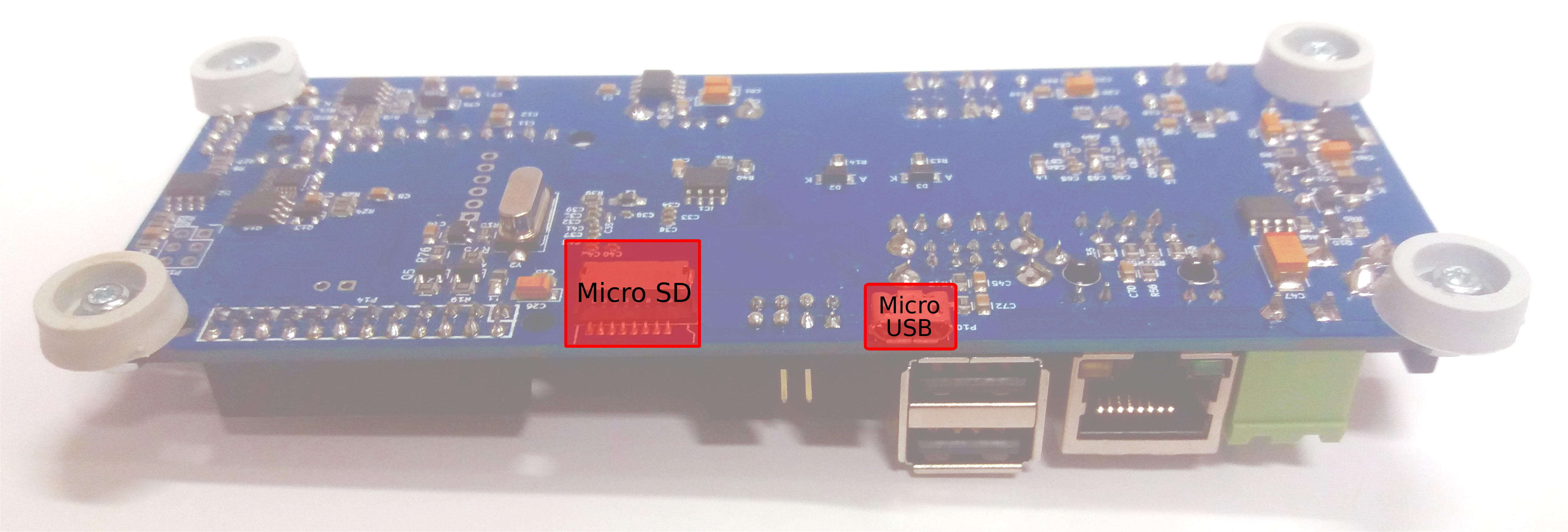
- Micro SD - slot for card controlled by SD-MUX part of MuxPi.
- Micro USB - NanoPi NEO UART0 (debug serial)
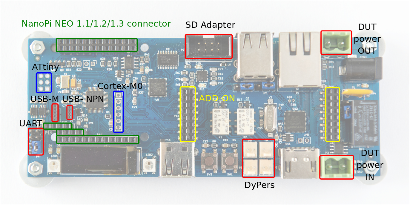
Other connectors
Below image shows the layout of all non-standard connectors.
- Green color is used to denote NanoPi NEO connector. It supports v1.1, v1.2 and v1.3 NanoPi NEO [2] board versions.
- Yellow color is used to denote MuxPi ADD-ON connector.
- Blue color is used to denote development only connectors, which are not described here. It is assumed that people who are interested in development of the firmware will refer to the schematics for pinout.
- Red color is used to denote rest of the connectors.
NanoPi NEO connector
NanoPi NEO is external module that is not subject to this documentation. Please refer to pinout of the NanoPi NEO [2] v1.1, v1.2 or v1.3.
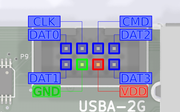
SD Adapter
This connector is used to hook the microSD card placed in to the MuxPi board (NOT NanoPi NEO) to the DUT. Name of pins follow the microSD standard thus are not explained here.
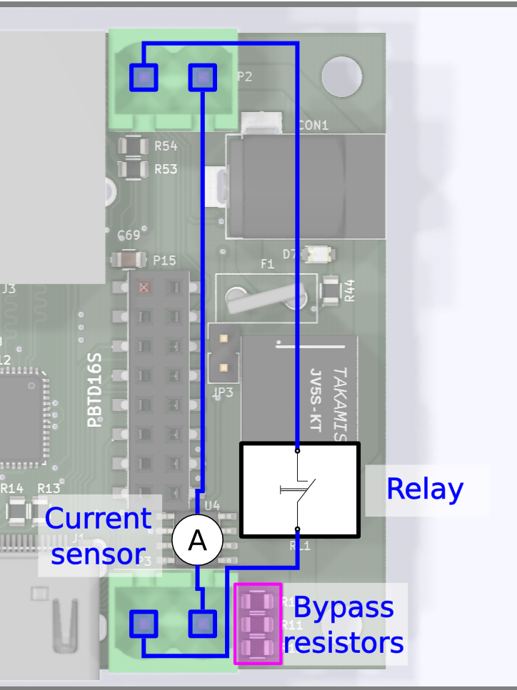
DUT Power
This component gives two features:
Power switch or a “hard resetter” for a DUT. This feature is realised using electromagnetic relay controlled by STM32. It can switch power supply up to 5A and 250VAC. One line is connected directly and one is connected through the relay.
Warning
It is not recommended to use this feature if DUT hasn’t been properly shut down as it might cause errors.
Current measurement - Muxpi is able to masure up to 5A. Current sensor is galvanically isolated from the rest of components thanks to use of Hall effect current sensor. It is connected to unswitchable power line.
Note
Current sensor is bypassed with 3 0R resistors that can be populated if current sensor is not needed. These resistors must not be populated if current measurement is required.
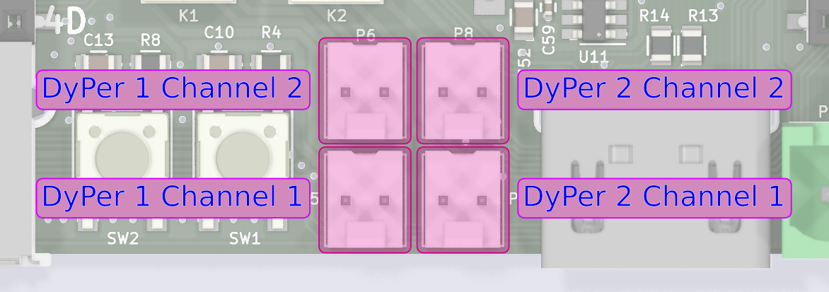
DyPers
Dynamic jumPers, so called DyPers, are simple programmatically controlled switches that can act as a regular jumper or a switch. It is meant to help automation when the jumpers or push buttons must be used on the DUT during normal operations such as powering on/off. Excellent example are ARTIK boards, which can’t be booted just by powering on. After applying power, the user is required to press “Power on” button. Such requirement would normally rule out automated testing.
Two-wire cable needs to be soldered to pins of the button (or connected to a jumper) and connected to one of DyPers. Using software it can be switched on and off what simulates pressing the button. Dypers are a small, electromagnetic relays There are 2 dypers on MuxPi board. Each of them has two channels. Both channels are switched at the same time with the same command. So both of them can be on and both can be off but there is no way to turn one on and one off. The two-channel design is useful for pairs of jumpers that need to be operated as pair. If for example some board needs to have 2 jumpers linked for flashing mode and 0 jumpers linked for normal operation then only one DyPer with two channels may be used. These two channels are separated galvanically so there is no worry that there will be some kind of influence.
Why electromagnetic realys instead of semiconductor switches? Because we don’t wan’t to deal with some relation of steering and operating signals.
Note
DyPers can be used for other purposes e.g. power switch - it can switch up to 0.5A signals.
UART
This is smart UART for connecting NanoPi NEO to a DUT. There is no need to use dedicated converters for particular boards because MuxPi has special level shifter which takes care for adjusting voltages of UART lines for both sides: NanoPi and the DUT. To take advantage of this shifter, pin VCC must be connected to power pin on DUT’s board. Voltage shifters have operating range from 1.6 to 5.5V. This is 4-wire UART which means that it can communicate using hardware flow control.
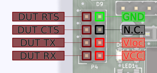
GND - digital ground of MuxPi board
N.C. - not connected
Vloc - local voltage
Voltage may be generated internally on MuxPi if the DUT, or anything else we are connecting to, has no power pin. In such case voltage generator must be set to desired value and activated. Command “uart 3300” must be sent to Cortex-M0, where 3300 is desired voltage given in millivolts. Supported voltage range is from 0 to 5000mV. Vloc an VCC pins must be connected in such case, e.g. with a jumper. Vloc may be also used to power up additional converter e.g.to RS-232C (+/-12V).
VCC - power of DUT. If dut has no such power pin then it must be connected to Vloc which must be confgured properly (as stated above).
DUT RX - receiver data line in the DUT - through this line MuxPi sends data to the DUT
DUT TX - transmitter data line in the DUT - from this line MuxPi reads data form the DUT
DUT CTS - Clear To Send - hardware handshake
DUT RTS - Ready To Send - hardware handshake
Warning
RX, TX, CTS, RTS are shown from DUT perspective so you don’t need cross the wires yourself.
Note
A device powered from Vloc must not draw more than 50mA of current.
Example connection to RS232 converter
Below image shows how to connect UART of MuxPi to a device. In this particular case it is 4-wire RS232C converter which must be powered from external source (from converter’s point of view). As stated above, wire cross is done on MuxPi board so cable should not be crossed. However in this image you can see cross because of strange labeling of pins on the converter.
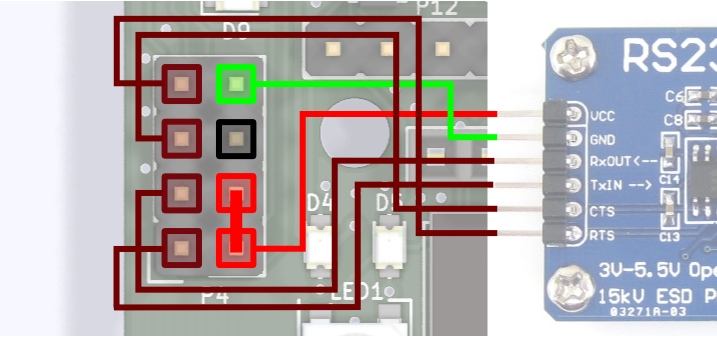
You can see in the image that Vloc and VCC are connected. In this example Vloc is used to power up the converter and bias the level shifters (VCC).
USB-M
This USB connector is dedicated to mobile Samsung devices. It has controllable Vbus and ID lines.
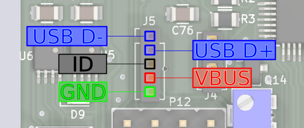
- USB D- - USB data line.
- USB D+ - USB data line.
- ID - pin controllable by MuxPi. A resistor with specified value can be connected to this pin or it may by left unconnected
- VBUS - +5V power line. It can be switched on and off.
- GND - ground line.
This connector is an endpoint of larger entity which is dedicated to connect to mobile devices. Thanks to its controllable Vbus and ID lines it is possible to control connected devices. It comprises of:
- ID switch with connected 1M multi-turn potentiometer - ID can be connected to ground through potentiometer or left open. The potentiometer has 11 turns. its value can be easily set using ohmmeter.
- Vbus switch thanks to which power can be switched on and off. This functionality is necessary to control connected device (power off, power on, download mode, etc.)
- UART/USB switch which allows to redirect mobile’s USB data lines either to NanoPi’s USB or to MuxPi’s DUT UART.
All of those components are independently controlled by Cortex-M0 microcontroller. For example if there is a need to reflash a mobile device, following steps needs to be taken:
- switch off VBus
- disconnect the battery of the mobile device - power switch of MuxPi can be used to accomplish this task
- connect resistor (potentiometer) to ID pin - potentiometer should be set to the correct value before the whole procedure is started. The value should be valid for UART mode.
- connect USB data lines of the mobile device to NanoPi by setting UART/USB switch to UART mode
- connect the battery to the mobile device
- switch on the VBus power
- send enter key code to the serial to stop u-boot
- send ‘thordown’ command to u-boot through serial connection (UART) - after this command the mobile device will switch USB data lines to USB automatically
- connect data lines of the mobile device to USB of NanoPi by setting UART/USB switch to USB mode
- start lthor/heimdall software to flash the device
- after flashing is finished switch off VBus
- disconnect the battery
- disconnect resistor from ID pin
- connect the battery
- switch on the VBus
- the device should boot with the new binary image and USB connection can be
- used to run tests.
This is an example which perfectly works with Samsung mobile devices. However, it should be possible to execute similar procedure with products of other brands if they support it.
Note
Special USB cable needs to be used as commonly available cables do not have ID pin connected. Micro USB connector pinout can be found on the internet and pinout of MuxPi connector is shown above.
ADD-ON connector
MuxPi can be easily extended by connecting add-on boards to it. There is a reference add-on which serves as universal starting point to design custom addon.
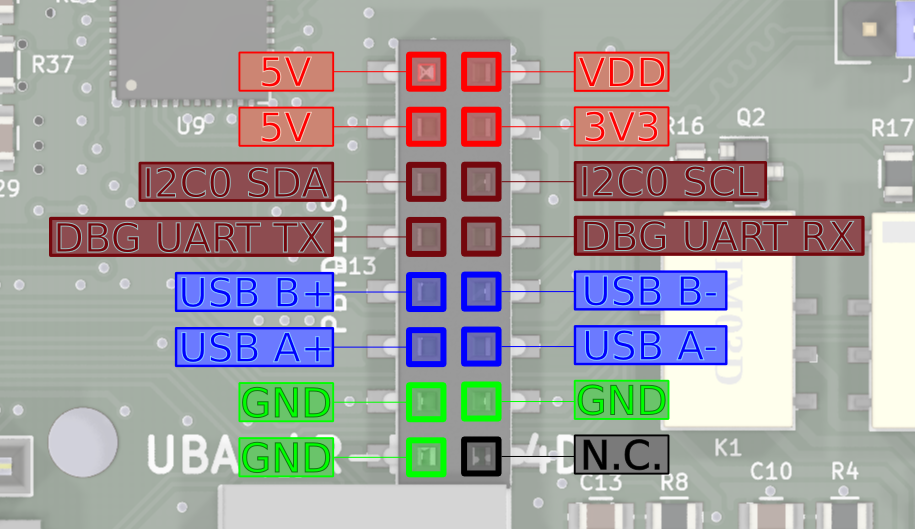
Above image shows left connector of the ADD-ON
- 5V - power supply - not switchable - always present
- 3V3 - switchable (controlled by NanoPi) 3.3V power supply
- I2C0 SDA - I2C0 SDA line connected to NanoPi
- I2C0 SCL - I2C0 SCL line connected to NanoPi * DBG UART TX - UART0 (debug) of NanoPi
- DBG UART RX - UART0 (debug) of NanoPi
- USB B+/-, USB A+/- USB host lines connected to NanoPi through USB HUB
- GND - ground lines
- N.C. - not connected
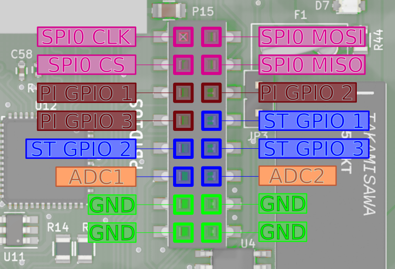
Above image shows right connector of the ADD-ON
- SPI0 CLK - SPI0 clock line connected to NanoPi
- SPI0 MOSI - SPI0 “master output slave input” line connected to NanoPi
- SPI0 CS - SPI0 “chip select” line connected to NanoPi
- SPI0 MISO - SPI0 “master input slave output” line connected to NanoPi
- PI GPIO 1,2,3 - GPIO (General Purpose Input/Output) connected to NanoPi NEO. Ports PG11, PL11, PA17 respectively.
- ST GPIO 1,2,3 - GPIO connected to Cortex-M0 microcontroller. Ports PB3, PB4, PB5 of STM32F03C6T6 respectively.
- ADC1,2 - analog inputs connected to analog to digital converter of Cortex-M0 microcontroller. Ports PA1, PA2 respectively. Voltage range of this input is 0 to 3.3V. This lines are not buffered in any way so attention must paid when dealing with them.
- GND - ground lines
Note
NanoPi’s GPIO 1 has additional special function. It is connected to Cortex-M0 Boot0 pin which enables firmware download mode during microcontroller boot. 1 - enables this mode while 0 disables it. So it is useless as GPIO when the microcontroller is being booted
Jumpers
There are 4 jumpers on the MuxPi board.
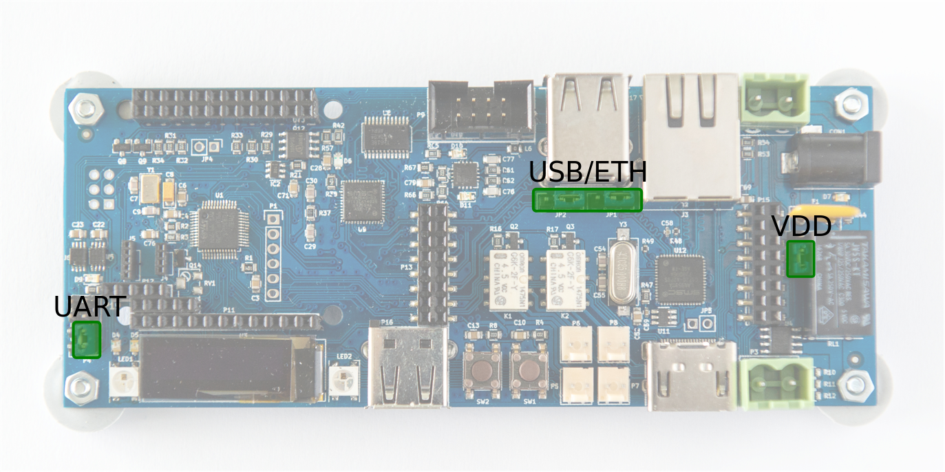
UART - pins Vloc & VCC - if jumped then internal voltage generator is used as voltage reference for data lines and powers up target device. If open then voltage reference for data lines comes from target device and internal voltage generator is unused.
USB/ETH - determines what USB data lines of one USB HUB are connected to. One downstream channel, outgoing from onboard USB HUB, is always connected to upper socket of double USB-A connector. It can be also connected to either add-on connector or onboard USB<->ETH converter. If first two pins are jumped then USB lines are connected to add-on connector. If last two pins are jumped then these lines are connected tu USB<->ETH converter. If none of the pins are jumped then the only connection is the upper socket of double connector.
Note
The upper socket of double USB-A connector must be lefty empty if USB<->ETH is selected or add-on connector is selected and something is connected to these data lines on the addon!
Warning
Both jumpers must be placed in the same position!
VDD - if this pins are jumped then the VDD and 3V3 are always on. If this is left open then VDD and 3V3 are controlled by NanoPi. Having the voltage always on may be helpful when MuxPi is to be used without NanoPi NEO board. The best example is setting value of USB ID potentiometer. The potentiometer is located underneath NanoPi NEO so it must be removed in order to do the adjustment. But when NanoPi NEO is removed there is no way to turn on power for microcontroller. And that is the moment when VDD jumper comes into the action. Just simply connect pins with jumper and power is on. Don’t forget to take of the jumper after the work is done.
Note
If there is no particular need, it’s best to leave this jumper open.
User Interface
MuxPi, in contrast to SD MUX, has quite rich user interface. It can give some information to an operator as well as receive it.
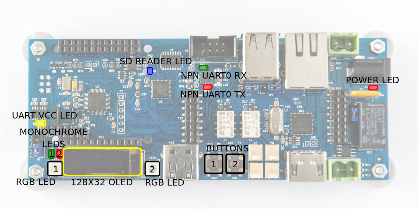
- POWER LED - red LED indicating presence of power supply
- SD READER LED - blue LED indicating internal SD card reader activity
- UART VCC LED - red LED indicating presence of UART target voltage
- (MONOCHROME) LED 1 - general purpose, green LED connected directly to NanoPi NEO GPIO
- (MONOCHROME) LED 2 - general purpose, red LED connected directly to NanoPi NEO GPIO
- RGB LED1, LED2 - two general purpose, RGB LEDs connected to Cortex-M0 microcontroller. Fully controllable by NanoPi NEO. These are WS2812B LEDs with builtin controller.
- 128x32 OLED Display - general purpose 0.96”, graphic display. Connected to Cortex-M0 and fully controllable by NanoPi NEO.
- BUTTON 1, 2 - two general purpose buttons connected to Cortex-M0 microcontroller. Fully accessible from NanoPi NEO.
- NanoPi NEO - not shown in the above picture. Keep-alive blue LED, mounted on NanoPi NEO board.
With this UI, an operator can be informed about current status of MuxPi and gently disturb it in order to perform some actions. Functions of UI are customizable and can be controlled from NanoPi NEO.
ADD-ONs
Add-ons are meant to:
- add functionality in the future, which was unknown during design process of MuxPi 8 add functionalities very rarely used (e.g. addon for USB ID potentiometer adjusting) - placing them on the board would be a waste of place.
A sample add-on was designed to provide board template for users specific boards.
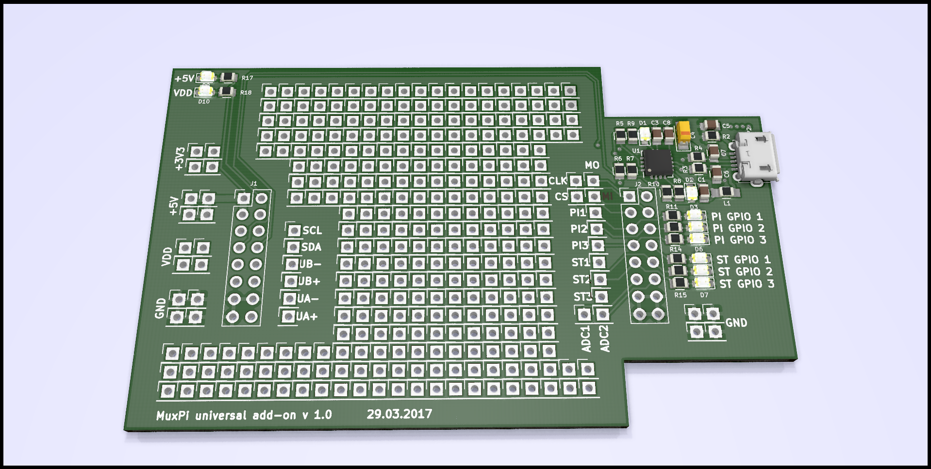
This add-on contains:
- LEDs connected to:
- 5V and VDD indicating power presence
- PI GPIO 1-3 indicating state of 3 NanoPi NEO GPIOs
- ST GPIO 1-3 indicating state of 3 Cortex-M0 GPIOs
- UART0 (NanoPi NEO) to USB converter
- lots of THT pads to ease soldering new circuits
Note
Its dimensions are as big as possible with special cutouts for power plugs.
Programmable units
Muxpi contains 3 programmable units:
- NanoPi NEO - the most advanced one. It is Linux based microprocessor.
- Cortex-M0 microcontroller - is responsible for low level actions and is only a slave for NanoPi NEO.
- ATtiny10 - a small AVR microcontroller which is used only a watchdog for NanoPi NEO.
All of the above units need software for the MuxPi board to function properly.
NanoPi NEO needs some distribution of linux on a micro SD card. You can find how to setup and configure a linux distibution on other pages in this documentation.
Cortex-M0 needs a firmware which is not available in the repo. There is the whole source code that can be built according to instructions that can be found in INSTALL file. There are also ready to flash binaries that are useful when a user does not wan’t to build one on their own. There are two ways to flash the microcontroller:
- flash it using some kind of SWD interface
- flash it from NanoPi NEO
Second solution is preferred as there is no single hardware nor software tool required. All what needs to be done is to download the binary and execute flash_firmware script with the file name as argument. It is true only if distribution of NanoPi NEO contains proper software. To be sure just use MuxPi dedicated distribution.
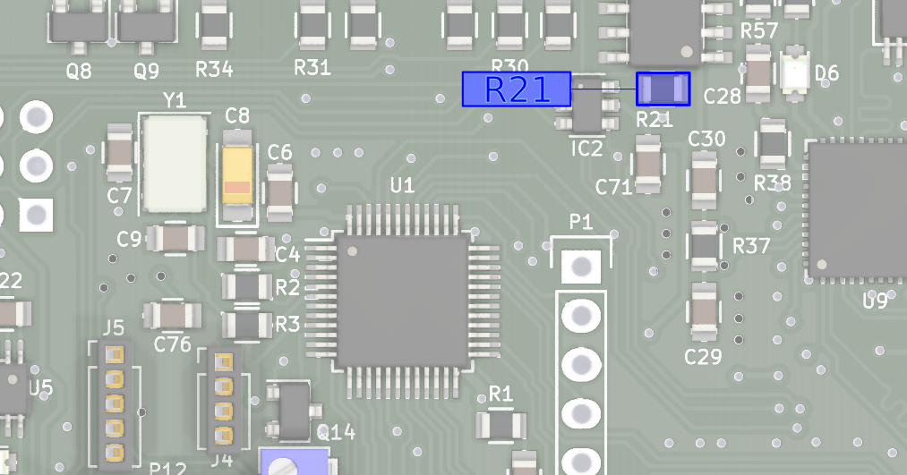
ATtiny10 microcontroller also needs firmware. Unfortunately this one needs special interface e.g. USBasp [3] or any other interface which is able to flash this microcontroller over TPI interface. Also for this microcontroller there is a full source code and ready to flash binaries. If watchdog functionality is not desired then instead of flashing firmware into ATTiny, R21 can be removed from MuxPi board. In such situation NanoPi NEO will always be powered on.
| [1] | https://en.wikipedia.org/wiki/Extended_Display_Identification_Data |
| [2] | (1, 2) http://wiki.friendlyarm.com/wiki/index.php/NanoPi_NEO |
| [3] | http://www.fischl.de/usbasp/ |